Lane and Bypass Marking
This chapter provides commanders with an Army-wide standard system for lane and bypass marking. It centers around a systematic, phased upgrade of lane marking. Each upgrade conforms to tactical requirements for that phase of the attack, from initial obstacle reduction to the passage of larger follow-on forces and the return traffic necessary to sustain the force. Lane or bypass marking is a critical component of obstacle reduction. Effective lane marking allows commanders to project forces through an obstacle quickly, with combat power and C 2 intact. It gives an assault force and follow-on forces confidence in the safety of the lane and helps prevent unnecessary casualties.
Lane-Marking System
3-1. There are two critical components to any lane-marking system—the lane-marking pattern and the marking device.
- Lane-marking pattern . The location of markers indicating the entrance, the lane, and the exit.
- Marking device . The type of hardware emplaced to mark the entrance, the lane, and the exit.
3-2. The lane-marking system outlined in this chapter centers on standardizing the marking pattern across the Army rather than standardizing the marking device. Standardizing the marking pattern is critical to offensive operations. A common lane-marking pattern—
- Enables cross attachments and adjacent units to recognize lanes easily with minimal knowledge of a particular unit's tactical SOP.
- Gives all forces a standardized set of visual cues needed to pass through a lane safely and maintain their momentum.
- Facilitates quick conversion to the lane-marking requirements of STANAG 2036.
3-3. Until the Army adopts a standard lane-marking device, commanders decide what hardware to use. This gives units greater flexibility, allowing them to adopt a marking device that is tailor-made for their type of unit and mission (armored or light force, mounted or dismounted attack, limited visibility, thermal capability). Regardless of the device used, it must support the standard lane-marking pattern outlined in the following paragraphs. Therefore, commanders should consider the marking guidelines and examples in this chapter before developing or adopting their own system. Commanders should determine and standardize the marking device used based on the availability of resources and METT-TC.
Lane-Marking Terms
3-4. The following terms provide a common basis for discussing lane marking:
- Entrance markers.
- Handrail markers.
- Exit markers.
- Entrance-funnel markers.
- Final-approach markers.
- Far-recognition markers.
- TCPs and guides.
Entrance Markers
3-5. Entrance markers indicate the start of a lane through an obstacle. They signify the friendly-side boundary of the obstacle and the point at which movement is restricted by the lane width and path. Entrance markers also indicate the lane width. Therefore, it is critical for a maneuvering force to distinguish the entrance point clearly, since it signifies the point at which passing vehicles can no longer adjust their movement in reaction to the situation (direct and indirect fires) without jeopardizing the force. Entrance markers must be visually different from handrail markers to help a force distinguish this critical point in the lane. The distance between entrance markers must be the same as the width of the created lane. Entrance markers placed a minimum of 4.5 meters apart indicate a lane capable of supporting mounted movement, while markers placed a minimum of 1 meter apart indicate a dismounted lane. When obstacle boundaries are vague or unknown, such as a buried minefield, the breach force uses its best judgment and marks the entrance where obstacle reduction and lane proofing begin.
Handrail Markers
3-6. Handrail markers define the lane path through an obstacle and indicate the limits of the lane width. As a minimum, mounted and dismounted lanes have a left handrail. Mounted and dismounted forces moving through a lane should keep the left handrail immediately to the left of their vehicle or person. The lane width is defined by the entrance markers. Therefore, when only the left handrail is marked, drivers use entrance and handrail markers to gauge the lane width and path. As the operation progresses, lane marking may be upgraded to include left and right handrails.
Exit Markers
3-7. Exit markers indicate the far side limit of a lane through an obstacle. For a passing force, the exit marker signifies the point at which movement is no longer confined to the lane path. Like entrance markers, exit markers must be distinguishably different from handrail markers; however, the exit may be marked the same as the entrance. Exit markers are placed to the left and right of an exit point and spaced the width of the reduced lane. This visual reference is critical when only a left handrail is marked. The combination of entrance, left-handrail, and exit markers gives the driver and the tank commander visual cues (entrance and exit points, lane width and path) to pass safely along a lane.
Entrance-Funnel Markers
3-8. Entrance-funnel markers augment entrance marking. The V formed by the funnel markers forces approaching platoons into a column formation and assists drivers and tank commanders in making last-minute adjustments before entering the lane.
Final-Approach Markers
3-9. Final-approach markers are highly visible, more robust markers that augment the visual signature of entrance-funnel markers. Units must be able to see the entrance funnel and/or the entrance-funnel markers from the final-approach marker. The final-approach marker—
Far-Recognition Markers
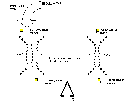
3-10. Far-recognition markers are highly visible markers located between the final-approach marker and the friendly unit. They are primarily used when passing battalion-size forces through a lane where direct observation of the final-approach marker is denied due to distance, visibility, or terrain. Far-recognition markers should be different from the final-approach marker. Far-recognition markers indicate the point at which forces begin changing their formation to posture for the passage. A single far-recognition marker may serve up to two lanes when located 200 to 400 meters apart. Once lanes are upgraded to two-way traffic, far-recognition markers are required for each two-way lane. Far-recognition markers should be visually alterable so that they can be distinguished from the far-recognition marker of an adjacent lane. This assists the C 2 of large formations when passing on several adjacent lanes. When a far-recognition marker serves more than one lane, a guide or a TCP is collocated with the far-recognition marker nearest the obstacle.
Traffic-Control Posts and Guides
3-11. A TCP or a guide is a two-man team with communications means that assists the commander in controlling the movement of forces. When available, consider using MPs to establish and man these posts. Initially, the commander may use other personnel as guides to man critical far-recognition markers until MPs establish full TCPs. TCPs and guides provide the commander with a means to control traffic flow to appropriate lanes. When there are multiple lanes branching off a single far-recognition marker, the TCP helps direct the formation to various lanes. The TCP can also assist in modifying the traffic flow when lanes have been closed for maintenance, for lane expansion, or by enemy SCATMINEs. The TCP or guide must give the commander the azimuth and distance to the final-approach marker, the device used for the approach marker, and the level of the lane-marking pattern. For light forces, guides may physically escort passing units from the far-recognition marker to the lane entrance. In short, the TCP allows the commander to make last-minute changes in the traffic flow, giving him increased flexibility to react to the enemy situation.
3-12. Another technique to facilitate the movement of the assault force to the points of breach is for the assault force to maneuver a recon element, such as a section, behind the breach force. This section observes the breach effort, identifies lanes, and leads the assault force to lanes after the breach is complete.
Levels of Lane Marking and Patterns
3-13. There are three levels of lane marking—initial, intermediate, and full. Each lane-marking level provides an increase in lane signature and capability. Lane requirements change as a breaching operation matures from the passage of the assault force to the passage of larger follow-on forces. Initial lane-marking requirements are driven by the nature of the fight through the obstacle. Marking must be rapid, providing only the bare minimum signature needed to safely pass small units (company teams, platoons) that make up the assault force. This contrasts with lane requirements during later phases of an attack where larger units (battalion and above) are passed to subsequent objectives and mark improvements to be made. Two-way traffic becomes a priority for the simultaneous forward passage of combat units and return traffic (ambulances, empty supply vehicles) necessary to sustain the force. With the increase in traffic volume comes more diverse forces and levels of driver experience. Lane-marking limits must be clear to the most inexperienced driver or crewman; do not assume he has a knowledge of the unit's SOP. A fully developed lane must support two-way traffic and be completely marked.
3-14. Commanders must be aware of how the lane needs of a force change with the operation so that they can anticipate lane-marking and lane-capability requirements. Integrating the levels of lane marking into the overall breaching plan ensures that a unit's needs are satisfied. The forces necessary to mark and upgrade lanes must be allocated and tasked with that mission. The scheme of maneuver and the service-support plan are the basis for analyzing lane requirements. The following paragraphs describe lane-marking patterns in detail and provide guidelines on when a commander should upgrade lane marking and lane capability.
Initial Lane Marking
3-15. The breach force emplaces the initial lane-marking pattern immediately after the obstacle is reduced and, if required, the lane is proofed. This is a signal to the assault-force commander that the lane is ready for traffic. Initial lane marking is kept to a minimum, focusing on the markings needed to pass immediate assault forces (company teams and smaller) through the lane to seize the point of penetration on the farside objective. Normally, the assault force can observe the lane as it is being marked and does not need the greater visual signature of mature lane marking. The initial lane-marking pattern contains—
- Entrance markers.
- Left-handrail markers.
- Exit markers.
- Entrance-funnel markers.
- A final-approach marker.
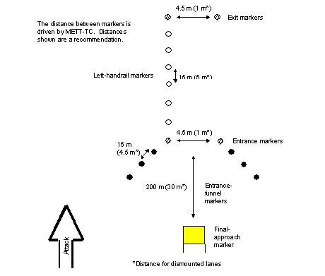
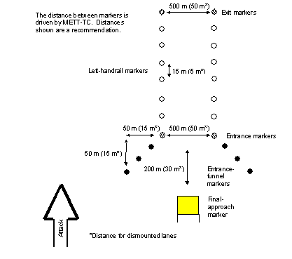
3-16. Figure 3-1 shows the initial lane-marking pattern. Entrance, left-handrail, and exit markers are the first markers that the breach force emplaces since these markers define the location and limits of the lane. These markers should be emplaced as follows:
- Entrance markers are placed to the left and right of the reduced lane's entrance point. They are spaced the width of the lane (at least 4.5 meters for mounted lanes and 1 meter for dismounted lanes).
- Left-handrail markers are placed at the left limit of the lane along the entire path. They are placed at 15-meter intervals for mounted forces and 5-meter intervals for dismounted forces. Commanders can modify the intervals based on the terrain, the visibility, the lane length, and the lane path. Additionally, commanders may choose to mark left and right handrails when the lane path is lengthy or unclear (through a complex obstacle).
-
Exit markers are placed to the left and right of the lane at the far side of the obstacle (at least 4.5 meters for mounted lanes and 1 meter for dismounted lanes).
|
|
3-17. After entrance, left-handrail, and exit markers are placed, the breach force emplaces entrance-funnel markers and the final-approach marker. These markers enhance the visual signature of the lane entrance for the assault force. If the assault force is in a position to observe the obstacle reduction, the commander does not have to wait until entrance-funnel markers and the final-approach marker are set to commit the assault force. However, the breach force continues to install the necessary markers to improve the lane signature for larger or subsequent follow-on forces maneuvering toward the lane. Entrance-funnel markers and the final-approach marker are emplaced as follows:
- Entrance-funnel markers are placed at 15-meter intervals for mounted forces and 5-meter intervals for dismounted forces. They are placed diagonal to the lane entrance to form a 45-degree V as shown in Figure 3-1 .
- The final-approach marker is centered on the lane and placed at least 200 meters from the lane entrance for mounted forces. For dismounted forces, the nature of the attack may preclude using a final-approach marker initially. Place a final-approach marker 30 meters from the entrance as soon as the mission allows. Commanders modify the recommended distance for the final-approach marker based on the terrain and the visibility.
Intermediate Lane Marking
3-18. Upgrading initial lane marking to intermediate lane marking is triggered by one of two key events—
- Commitment of larger combat forces who are unable to directly observe the obstacle as it is reduced.
- Rearward passage of sustainment traffic (casualty evacuation and vehicle recovery).
3-19. Intermediate lane marking has two goals—
- Increasing the lane signature to assist in the passage of larger combat forces.
- Providing sufficient marking for two-way, single-lane traffic.
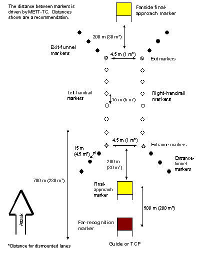
3-20. Intermediate lane marking builds on the initial lane-marking pattern by adding right-handrail markers, exit-funnel markers, far-recognition markers, and a farside final-approach marker. Figure 3-2 shows the intermediate lane-marking pattern.
|
|
3-21. The commander sets the priority of marker emplacement based on the situation. If the scheme of maneuver requires the immediate passage of larger combat forces, right-handrail markers and the far-recognition marker may be the priority. On the other hand, if it is necessary to ground-evacuate casualties or to recover vehicles, it may require emplacing right-handrail markers, exit-funnel markers, and the farside final-approach marker first. Intermediate lane marking gives the commander greater flexibility. Establishing a network of guides becomes increasingly important to direct the flow of forward and returning forces.
3-22. Regardless of the reason for an upgrade, the first step is to emplace right-handrail markers. These markers define the rightmost limit of the lane. They are placed the width of the lane as defined by entrance and exit markers. The right handrail follows a path parallel to the left handrail through the obstacle. Right-handrail markers are placed at the same interval as left-handrail markers.
3-23. Exit-funnel markers and a farside final-approach marker are emplaced to mirror entrance markers. For the forward passage of large combat forces, exit-funnel markers prevent the premature deployment of a passing force into combat formation before it is safely outside the obstacle. Exit-funnel markers also become entrance-funnel markers for rearward passing traffic, giving these forces the visual cues needed to align themselves on the lane. Exit-funnel markers are augmented by a farside final-approach marker to help rearward passing forces clearly identify the lane from their side. The farside final-approach marker is centered on the lane and placed 200 meters (30 meters for dismounted forces) from the exit (farside entrance).
3-24. A far-recognition marker completes the intermediate lane-marking pattern. It provides commanders with a visual signature or a series of signatures on which to guide their movement toward the lane. When the assault force is moving over a greater distance to the lanes, additional far-recognition markers may be required. For mounted forces, the far-recognition marker nearest the obstacle is placed a maximum of 500 meters from the final-approach marker (the final-approach marker must be visible from the far-recognition marker). Dismounted forces may require a system of guides instead of far-recognition markers for passing combat forces. However, far-recognition markers must be emplaced as soon as possible to reduce guide requirements for passing mounted sustainment traffic. This gives the assault-force commander the space needed to transition to a column formation.
3-25. A commander collocates guides or TCPs at the far-recognition marker when he feels the situation requires more positive control over traffic flow. Normally, the need to increase traffic control comes at the same time as the need for limited two-way traffic and intermediate lane marking. Commanders should plan for the use of dedicated guides once they have upgraded to intermediate-level marking. Guides or TCPs become mission critical during limited visibility or in restrictive terrain. They should also be used when a single far-recognition marker feeds more than one lane. TCPs must be manned with a minimum of two soldiers and must have secure frequency-modulated (FM) communications with the controlling HQ. It is essential that soldiers acting as guides or TCPs know the—
- Azimuth and distance to the final-approach marker or the 8-digit grid coordinate of the final-approach marker that is entered into the unit's Global Positioning System (GPS) receiver.
- Lane-marking pattern currently emplaced.
- Type of final-approach marker used.
- Traffic-control plan and march order.
Guides must be kept up-to-date on the status of lane marking, maintenance, and closures.
Full (Two-Way) Lane Marking
3-26. Lane marking is upgraded to a full lane-marking pattern when the commander desires uninterrupted two-way traffic flow. Expanding lanes to full lane marking is resource-intensive and is not part of a breaching operation. A full lane supports uninterrupted two-way traffic. The marking pattern is modified to give forces passing forward or rearward the same visual signature.
3-27. Upgrading to a full lane-marking pattern is normally assigned to follow-on engineer forces, since it is usually beyond the immediate capability of engineers with forward units. In special cases, the commander may task engineers with forward units to expand and upgrade a lane from an intermediate to a full lane-marking pattern. However, the trade-off is decreased support to forward units and delays associated with changing task organization. The full lane-marking pattern is also used when marking a lane through friendly obstacles along a main supply route (MSR) or a passage lane.
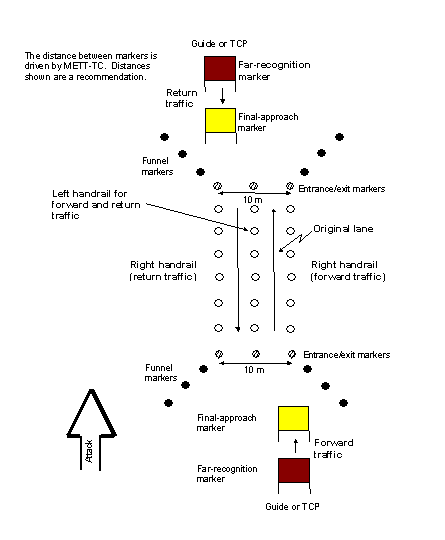
3-28. Upgrading intermediate lane marking to full lane marking begins by temporarily closing the lane, rerouting traffic, and expanding the lane width. The lane is always expanded to the left in relation to the direction of the attack. Engineers reduce and proof the obstacle beginning at the left handrail to give a total lane width of 10 meters (5 meters each way). The expansion width requirement is the same for armored and light forces, since both forces must be able to pass mounted sustainment and combat forces. When the lane is expanded by mechanical means, it is necessary to entirely remove the left-handrail markers during expansion. Whenever possible, these markers should be left alone to serve as a reference point during lane expansion. If removed altogether, left-handrail markers must be replaced since they form the left handrail for both forward and rearward passing forces.
3-29. When the lane width has been expanded to 10 meters, entrance, exit, right-handrail, funnel, and final-approach markers are replaced on the return lane. All markings are the same as described in previous paragraphs. Figure 3-3 shows a full lane-marking pattern.
|
|
3-30. The full lane-marking pattern has three entrance and three exit markers. Entrance and exit markers are placed the width of forward and return lanes and are visually different from other markers. Three entrance markers indicate a two-way traffic lane, and units should always use the rightmost lane. Entrance- and exit-funnel markers are placed slightly different from previous marking patterns. In the full lane-marking pattern, funnel markers extend out from the entrance and exit markers on the outside only. Final-approach markers are placed 200 meters from and centered on entrances of forward and return lanes. This helps forces identify entrance points from either direction. Far-recognition markers are placed a maximum of 500 meters from forward and return final-approach markers. Again, distances may be modified based on the terrain, the visibility, and the mission.
Commander's Guidance for Lane Marking
3-31. Table 3-1 provides the commander with a summary of lane-marking levels, guidelines on unit responsibilities, and events that trigger a lane-marking upgrade. The chart focuses on TF-level breaching operations. In the table, who refers to the unit responsible for lane marking, when describes events that trigger the need to upgrade, and markers highlight a quick reference for lane-marking requirements.
Movement Through the Lane
3-32. Standard lane-marking patterns help the commander in two critical aspects when moving a unit through a lane:
- Lane markers help the force posture its formation for efficient passage through the defile that is caused by the lane through the obstacle.
- The combination of lane markers and TCPs gives the commander greater flexibility in the forward and rearward movement of forces.
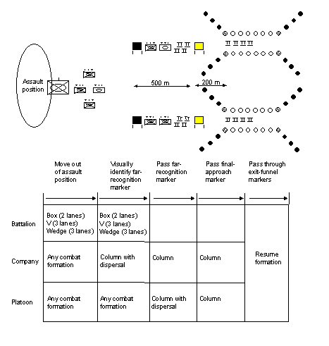
3-33. Far-recognition and final-approach markers in a standard lane-marking pattern help commanders smoothly change assault and follow-on forces into a column formation before passing through the lane. In most cases, the situation should allow the unit to move in a column formation from the outset; however, the enemy situation and the terrain may demand that forces remain dispersed as long as possible. Far-recognition, final-approach, and entrance-funnel markers are used to trigger commanders to alter their formations.
Figure 3-4 shows how formations at various levels may change to efficiently pass through lanes. A battalion TF initially moves from its assault position in a box, V, or wedge formation depending on the number of lanes being used.
|
|
3-34. Initially, company teams and below may move in any combat formation. Once lead elements of the battalion visually identify the far-recognition marker, company teams begin moving into a column formation with platoons still deployed. Platoons—
- Change into a column formation with dispersal as they move from the far-recognition marker to the final-approach marker.
- Change into a column formation as they move from the final-approach marker to entrance markers, using the entrance-funnel markers as guides.
- Redeploy once they pass through the exit or the exit funnels.
3-35. As the operation progresses, commanders should upgrade lane marking and establish traffic control as early as METT-TC allows. The combination of upgrading lanes from the initial marking pattern and establishing TCPs gives the commander greater flexibility. Normally, TCPs are established at forward and return far-recognition markers. Upgrading to full lane marking that is capable of supporting uninterrupted two-way traffic is generally determined by the need to pass increased volumes of traffic.
3-36. Figure 3-5 shows the flexibility that full lane marking and TCPs provide. In this example, friendly forces have created two lanes, 200 meters apart. Lane 1 is a full lane, and lane 2 is an intermediate lane. A far-recognition marker on the nearside and the farside can feed traffic to both lanes. Full lane marking and TCPs allow the commander to continue pushing combat power forward on lanes 1 and 2 simultaneously. At the same time, the farside TCP directs all return traffic to lane 1. Commanders should ensure that recovery vehicles are on site to remove immobile and destroyed vehicles.
|
|
Lane Maintenance and Responsibilities of Traffic
Through Lanes
3-37. As discussed in Chapter 2 , units must plan for lane maintenance (widen lanes, upgrade lane markings, ensure that lanes remain open, ensure C 2 of traffic through the breach area). The responsibility for lane maintenance should be delineated in unit orders to ensure alignment with the scheme of maneuver. Specifically, units must determine who is responsible for—
- Maintaining lanes in tactical and protective obstacles.
- Maintaining lanes when a change occurs.
- Controlling traffic within the breach area.
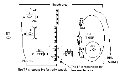
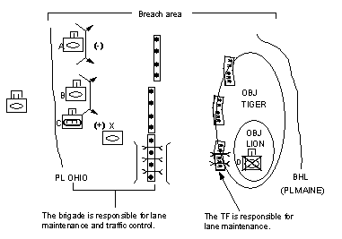
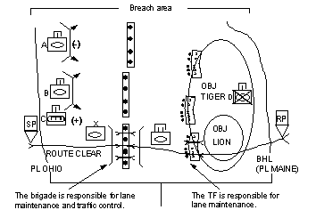
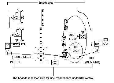
3-38. Figures 3-6 through 3-9 show how a unit defines responsibilities for lane maintenance and traffic control. In this example, a TF breaching operation is being conducted. Teams A and B provide suppressive fires as the support force, Team C reduces tactical obstacles as the breach force, and Team D seizes OBJs LION and TIGER as the assault force. The brigade intends to pass an armored TF through obstacles as the first element of the follow-on forces once the TF has cleared a route through the breach area. Note that the initial-lane requirement to pass Team D (the assault force) is one vehicular lane, but the breach force breaches a second lane to pass follow-on forces (an armored TF).
|
|
|
|
|
|
|
|
3-39. As the breaching operation progresses, the breach force creates two lanes in the tactical obstacles. The breach force marks lanes with the initial lane-marking pattern and passes the assault force through the lanes ( Figure 3-6 ). At this stage of the breaching operation, the TF maintains lanes in the tactical obstacles and controls all movement of forces within the breach area.
3-40. The assault force passes through the tactical obstacles and attacks to seize OBJs LION and TIGER. As the assault force attacks, it encounters protective obstacles and reduces and marks them. Immediately after the assault force passes through the tactical obstacles, the brigade assumes responsibility for lane maintenance in the tactical obstacles. The brigade also assumes responsibility of traffic control from the beginning of the breach area through the tactical obstacles. This includes creating additional lanes, ensuring that the lanes remain open, upgrading lane markings at the tactical obstacles, establishing TCPs, and calling units forward into the breach area. The TF is responsible for maintaining lanes through the protective obstacles ( Figure 3-7 ).
Once the assault force has seized its objective and reported that it has established a clear route up to the BHL (PL MAINE), the brigade begins to pass the follow-on TF through the breach area. At this point, the brigade controls traffic throughout the breach area. The TF is responsible for maintaining lanes in the protective obstacles ( Figure 3-8 ).
3-42. As the follow-on forces cross the BHL, the breaching operation is complete; however, the obstacles within the breach area remain a constriction for other follow-on forces. At this point, the brigade maintains lanes and controls traffic. The brigade begins to focus on establishing MSRs through the breach area using corps engineer assets, which are task-organized to the brigade from the division ( Figure 3-9 ).
Lane-Marking Devices
3-43. Currently, the Army has no standard lane-marking device. The current marking systems in the Army's supply system are—
- Hand-Emplaced Minefield Marking System (HEMMS), national stock number (NSN) 9905-01-019-0140.
- Minefield Marking Set Number 2, NSN 9905-00-375-9180.
- Cleared-Lane Marking System (CLAMS), NSN 2590-01-205-3082.
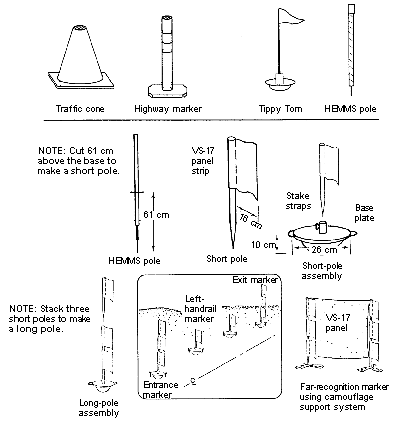
3-44. Most lane marking in the field is done with nonstandard marking devices. Before adopting a nonstandard marking device, commanders should consider the guidelines summarized in Table 3-2 . Coordination must occur between forces who are tasked to mark lanes and forces who are expected to use lanes to ensure that the marking material will work. For example, if a light force plans to create and mark vehicle lanes with an infrared light, vehicle drivers with enhanced (thermal) night-vision devices may not be able to see the markings.
Figure 3-10 shows some of the devices that units currently use; they are easily procured or fabricated. This is by no means a complete listing; rather, it is intended to show commanders some of the options. Some of the general requirements for lane marking are—
- Markers must be able to withstand the rigors of the terrain, the weather, and the battle space.
- Markers should be easy to modify when visibility is limited, with minimal addition of manpower and equipment.
- Enhancements for limited visibility should be a constant source rather than a pulsating strobe. Strobes do not make the marking pattern readily apparent, particularly when approaching from an angle.
|
Bypass Marking
3-46. Bypasses are marked using the same lane-marking patterns, marking devices, and visual cues as a lane. However, marking a bypass around an obstacle is much different from marking a lane through an obstacle because the amount of room available for forces to maneuver must be determined. While lanes through an obstacle are normally expanded to the left, bypasses are expanded away from the obstacle.
3-47. Bypasses must show where it is safe to rapidly pass around an obstacle, without unnecessarily restricting the force's ability to maneuver ( Figure 3-11). To accomplish this, the marking unit will mark the bypass with a bypass-marking pattern (modified initial lane-marking pattern with right-handrail markers added). The unit will recon and initially mark the bypass 500 meters wide to allow platoons to maneuver around the obstacle. The width of the bypass is increased as time allows further recon. Limited visibility or additional obstacles discovered at the flank of the obstacle that is being bypassed may constrain the marked width of the path to less than 500 meters. (The right-handrail markers must be visible from the left-handrail markers.) In addition to bypass marking, units should consider establishing mobile guards on the friendly side of the obstacle to prevent vehicles/personnel from entering it. All units on the battle space should possess marking material and understand how to emplace the bypass-marking pattern.
|
|
Marking Requirements Under the North Atlantic
Treaty Organization
3-48. The following paragraphs paraphrase the breach lane-marking requirements outlined in North Atlantic Treaty Organization (NATO) STANAG 2036. They also establish procedures used by US forces to modify intermediate and full lane-marking patterns to STANAG standard. The trend in modern warfare is increasing toward combined operations, so commanders need to be aware of their responsibilities under the NATO standard for marking hazardous areas, particularly lanes through obstacles.
Commanders' Responsibilities
3-49. STANAG 2036 outlines the minimum requirements for the lane-marking pattern before troops of other nations use the lane. Commanders must plan to convert the lane to the NATO marking standard as early as possible. When converting to the NATO standard, STANAG 2036 directs commanders to use the lane-marking devices as stated below. Within an offensive operation, this does not normally occur until the lane is matured to a full lane.
Marking Patterns and Devices
3-50. The intermediate lane-marking pattern satisfies the minimum lane-marking pattern that must be used before forces from another country pass through a lane. STANAG 2036 states that the entrance point, the exit point, and left and right handrails are the minimum required lane signatures. Furthermore, STANAG 2036 requires that the entrance and exit of a lane be distinguishably different from other markers and that handrail markers be placed at intervals no greater than 30 meters. These requirements are met once lane marking is upgraded to the intermediate or full lane-marking pattern. Once the lane is marked to the the intermediate level, commanders can use the lane for allied forces to pass through without any additional marking if proper marking material is used.
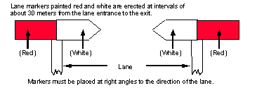
3-51. Figure 3-12 shows a NATO standard marker. The marker is placed at a right angle to the direction of travel so that the white portion of the arrow points inward to the lane, indicating the safe side on which to pass. The red portion points outward, indicating the lane limit or dangerous side of the lane. Units may fabricate NATO markers if they cannot get them through the supply system. STANAG 2036 requires that markers be visible from 50 meters under all conditions.
|
|
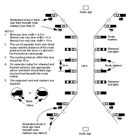
3-52. To convert intermediate lane marking to the NATO standard, affix NATO markers to long pickets and replace the existing entrance, exit, funnel, and handrail markers one for one. Figure 3-13 shows how NATO markers are used to convert an existing intermediate lane-marking pattern. Two NATO markers are used for entrance and exit markers to make them distinctly different. One NATO marker is affixed to each funnel marker and to each left- and right-handrail marker.
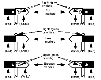
NATO uses white or green lights to illuminate markers at night. Entrance and exit markers are marked with two green lights or two white lights, placed horizontally, so that safe and dangerous markings on them are clearly visible. One white light or one green light is used on funnel and handrail markers. Commanders decide whether the light is placed on top of the NATO marker or placed so that it illuminates the marker ( Figure 3-14). Lights must be visible from 50 meters under all conditions. Light sources for nighttime markers must have a continuous life of 12 hours.
|
|
Complex Obstacles
3-54. When marking lanes through a complex obstacle, units can mark each obstacle independently or mark the entire obstacle system at once. The depth of the obstacle system, the distance between the obstacles, and the amount of marking material available determine which method is employed. See Figures 3-15 and 3-16 for examples of how complex obstacles may be marked; the examples use the initial lane-marking pattern.
|
|
|
|
