Route Clearance
Route clearance is a combined-arms operation typically executed by an infantry company or a cavalry troop. Units must clear lines of communication (LOC) of obstacles and enemy activity that disrupt battle-space circulation. Units must conduct route clearance to ensure that LOC enable safe passage of combat, combat-support (CS), and CSS organizations. Clearance operations are normally conducted in a low-threat environment.
Methods and Levels
E-1. The information gathered from the IPB and the recon effort determines the method and type of route clearance to conduct. The determination is based on the situation, the time available, the threat level, and available assets.
E-2. During stability and/or support actions, it is recommended that former-warring-faction (FWF), engineer-equivalent clearance teams precede US clearance teams within the FWF's AO. Do not assume that FWF clearance teams will be thorough in their clearance operation. Treat the route as unsafe until US or allied force clearance teams have proofed the route to confirm that it is cleared.
Clearance Methods
E-3. There are three methods of route clearance—linear, combat, and combat route. The method employed depends on the situation, the time available, and the clearance assets available. The maneuver force should always establish static security positions at critical locations following the completion of route clearance.
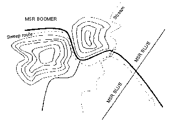
- Linear . In linear clearance ( Figure E-1), the clearance begins at checkpoint 1 and is completed at checkpoint 2. This method provides the best assurance of route clearance. Although this is an effective method, it is not the most secure method in a high-threat environment. It is also time-intensive and constrains the maneuver commander's flexibility.
Figure E-1. Linear Clearance Method
|
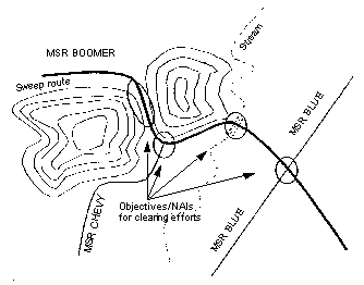
- Combat . Whereas linear clearance focuses on a specific route, combat clearance ( Figure E-2) focuses on specific points along a route. As mentioned previously, the IPB can identify likely areas for obstacle and ambush locations. These areas become NAIs or objectives for combat clearance missions. The combat clearance method divides a route into sections according to the number of suspected high-threat areas. Once the unit clears these areas, the route is considered clear. Combat forces can patrol the route from these objectives to ensure that the route is secure and, if necessary, the sweep element can sweep the surrounding area if a minefield is found. Following the seizure of these objectives, the commander must assume a moderate risk that the S2 and the force engineer have identified all high-threat areas and that the route is clear of obstacles.
-
Combat route . This method combines the clearance capabilities of the linear method with the security and surprise elements of the combat method. It is a two-phase, force-intensive operation and may require a battalion-size element, depending on the route's length. First, identified high-threat areas are targeted, secured, and cleared of obstacles and enemy forces before a sweep team moves. The sweep team then travels down the road and clears obstacles missed or not identified during the IPB/engineer battlefield assessment (EBA). The advantage of this method is that the TF commander immediately secures MSRs and then finds the enemy, confident that MSRs are relatively safe.
|
Sweep Levels
E-4. The four levels of sweep operations are discussed below. All four levels can be modified to meet the unit's time and equipment limitations, but the commander assumes greater risk when the clearance level is modified. All four sweep levels can be used with any of the three clearance methods (linear, combat, and combat route).
- Level one . This is the fastest, riskiest type of route sweep. It is ideal for an armored/mechanized team. The sweep relies primarily on visual detection, using thermal or infrared sights or the naked eye for mine identification. It is followed immediately by a secondary, mechanical detection system such as MCRs. The sweep team is a squad-size or larger element that is task-organized with mine detectors, demolitions, and possibly an interim vehicle-mounted mine detector (IVMMD). The sweep team looks for minefields along the road width of a route. Security and support teams consist of a maneuver platoon to provide overwatching fire. The primary objective of a level one sweep is speed, with the sweep team moving at 5 to 8 miles per hour. The sweep team identifies immediate risks to traffic, neutralizes those risks, and continues on with the mission. If mine rollers are not available, a sandbagged 2 1/2-ton truck driven backwards can be used for a level one sweep, but only as a last resort. In this situation, the mine rollers are only a means of detection, not breaching. Mine rakes or plows are not always satisfactory substitutes because they most likely will destroy road surfaces.
- Level two . A level two sweep uses electronic measures as the primary detection method in high-threat areas. These areas include intersections, choke points, and areas within 10 meters of wood lines. A level two sweep employs more caution and forces the unit to update the IPB before beginning the mission. This level of operation employs a company team for security and C 2 . Dismounted forces clear and secure the flanks and the far side of an identified minefield, while an engineer squad clears the road area.
- Level three . A level three sweep is more in-depth and more time-consuming. The sweep team must examine the route's entire width, including the shoulders and ditches. This technique ensures that follow-on forces are protected if they are forced to the side of the road. The security and support element also moves, mounted or dismounted, to provide rapid response and security. The sweep team provides a route recon report that updates current maps and further identifies high-threat areas. Staffs gain valuable information from this report for future operations.
- Level four . A level four sweep is very time-consuming. It relies on visual and electronic means for clearance. The platoon-size sweep team is dismounted to focus attention on the route's entire length. The company-size security element clears and secures the flanks and front of the sweep team (at least 100 meters in each direction in forested areas). This clears the area of off-route and command-detonated mines and allows the team to focus solely on the route. MCRs are used to proof the route after the sweep team passes through the area. Level four sweeps include route and area recons, and they are used when thoroughness and security, not speed, are critical to the mission.
Equipment
E-5. The IVMMD and the MinFlail are used to conduct route clearance.
Interim Vehicle-Mounted Mine Detector
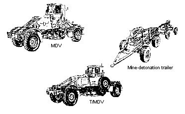
E-6. The IVMMD ( Figure E-3 ) is used in all levels of conflicts and stability and/or support actions. It is mounted on a blast- and fragmentation-survivable vehicle and is designed to detect and mark buried and surface-laid, metallic AT mines. The primary mission of the IVMMD is to detect mines during route-clearance operations. The system should not be operated in an environment where the enemy employs mines that are not pressure-fused.
|
System Components
E-7. A complete IVMMD consists of one mine-detection vehicle (MDV), one towing/mine-detection vehicle (T/MDV), three mine-detonation trailers, a spare-wheel module for the MDV, a spare-wheel module for the T/MDV, and a container of spare parts.
E-8. The MDV's only mission is to detect mines. It can negotiate vertical slopes up to a 20 percent grade. The MDV employs a 4-cylinder engine and a manual transmission to propel the 4.8-ton vehicle with a 3-meter-wide detection array. The detection array consists of two separate induction coils (one for the left side and one for the right side) that detect magnetic fields below the vehicle. The detection array is suspended between the two axles of the vehicle. When the detector encounters a metallic object, the operator is notified by an audible signal in the earphone and a visual signal on the dashboard that denotes which side array detected the object. The operator then stops the vehicle, backs it up, and reencounters the metallic object. (The MDV has two detection modes—the locate mode is used to identify the metal object, and the pinpoint mode is used to find the center of the object.) When the operator encounters the strongest signal, he activates the marking system (a nozzle mounted on the rear frame and centered on each detection array) that deploys a water-based ink onto the roadway.
E-9. The MDV is designed to produce very little ground pressure; however, it may detonate pressure-fused mines, depending on their fuse sensitivity. The MDV produces 27.9 pounds per square inch (psi) of ground pressure when the tires are inflated to 14.5 psi and 21.8 psi of ground pressure when the tires are inflated to 8.7 psi.
E-10. The T/MDV has a 6-cylinder engine and the same detection and marking system as the MDV. The T/MDV produces 49.8 psi of ground pressure when the tires are inflated to 29 psi and 23.4 psi of ground pressure when the tires are inflated to 8.7 psi. The T/MDV tows three mine-detonation trailers, and the recommended maximum operating speed while towing the trailers is 20 kph. The T/MDV (with trailers) can negotiate vertical slopes up to a 20 percent grade; however, going down such slopes is difficult. The T/MDV must be in first gear, and the trailer brakes must be deployed to decrease the speed of the vehicle when going down a slope.
E-11. The mine-detonation trailers are very heavy and specifically designed to apply heavy ground pressure that initiates pressure-activated mines. Each trailer has two axles of different lengths so that the three trailers provide a full 3-meter-wide proofing capability behind the T/MDV. If a mine detonates underneath the trailers, the wheel bolts are designed to sheer so that repair is limited to replacing a single wheel.
Employment Concept
E-12. The IVMMD is used to support route-clearance operations. Clearance operations ensure that LOC are safe for the passage of personnel and equipment. The IVMMD should not be used during hours of limited visibility, because it hampers the operator's ability to see surface-laid mines and visual signatures that indicate mining activities.
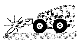
MiniFlail
E-13. The MiniFlail ( Figure E-4 ) is a remotely operated, LOS, AP-mine and unexploded-ordnance (UXO) neutralization system that was developed for use by US light forces. The MiniFlail detonates or disables AP mines from a safe operating distance. It neutralizes by striking objects with a rotating chain assembly, called a flail, and clears a footpath about 1.1 meters wide. The system neutralizes AP mines and UXO by detonation, mechanical destruction, or displacement from the cleared lane. The MiniFlail is about 1.3 meters wide, 1.3 meters tall, and 3 meters long; it weighs 1,100 kilograms. The system is operated by a hand-held controller that has a maximum range of 300 meters. It is fully armored with a material similar to Kevlar, and the tires are filled with foam. The MiniFlail is a self-articulating, hydraulically powered shaft with 84 chains; each chain is 0.5 meter long.
|
|
Planning
E-14. The principles of breaching operations apply to developing and executing the route-clearance mission. The breaching tenets (intelligence, fundamentals, organization, mass, and synchronization) are the basis for planning.
Intelligence
E-15. Incorporating the IPB and METT-TC factors into route-clearance operations enables units to predict what the enemy will do and where it will do it. After the S2 and the engineer identify the most probable threat sites, the S2 designates them as NAIs. These NAIs are the focus of the recon effort. Recon assets confirm the presence or absence of ambushes, UXO, and obstacles. The information gathered from the IPB and the recon effort determines the method and type of route clearance necessary. It also helps the commander determine any outside resources (explosive ordnance disposal [EOD] and special-operations forces [SOF]) that he may need.
Fundamentals
E-16. SOSRA may not be executed, but it is planned as it is in breaching operations. Units must be prepared to execute SOSRA fundamentals as necessary.
Organization
E-17. Route-clearance operations are similar to breaching operations; therefore, commanders should plan and coordinate breaching fundamentals to suppress, obscure, secure, and reduce obstacles. Task-organizing for route clearance is also similar to that required for breaching operations. The assault force becomes the security element, the breach force becomes the sweep element, and the support force remains the same.
E-18. The significant difference between breaching and clearing operations is that breaching usually occurs during an attack (while under enemy fire) to project combat power to the far side of an obstacle. Route clearance focuses on opening LOC to ensure the safe passage of combat and support organizations within an AO. Table E-1 shows a sample task organization for a route clearance.
Mass
E-19. Sufficient maneuver and engineer assets must be allocated to the sweep force. The length and width of the route and the type of clearance to be conducted determine the composition of the breach force. Clearing a Class A military road with the deliberate sweep technique requires at least two IVMMDs and/or two engineer squads due to the total lane width to be cleared and the requirement for rotating mine-detector operators. Depending on the type of sweep operation, the commander should plan for a 50 percent loss of sweep assets.
Planning Considerations
E-21. The purpose of breaching is to project combat power to the far side of an obstacle, and breaching usually occurs under enemy fire. Route-clearance operations focus on opening and maintaining LOC to ensure the safe passage of combat, CS, and CSS organizations. Like breaching, route-clearance operations require extensive Battlefield Operating System (BOS) coordination. The planning considerations shown in Table E-2 should be used by brigade and battalion TFs when planning route-clearance operations. The obstacle template produced from this process determines which method and type of route clearance is required.
|
Identify choke points, bridges, tunnels, critical road junctions, and built-up areas. These are the most likely locations for obstacle emplacement. However, depending on the enemy's overall mission, it may not always emplace obstacles at these locations. This is especially true if the enemy's goal is to psychologically disrupt convoys. |
|
Maintain a situation map that reflects the most current intelligence information. |
|
Maintain an incident map with a graphics overlay to facilitate a pattern analysis. |
|
Maintain a threat order-of-battle database, such as how the enemy has disrupted LOC in the past. |
|
Develop a detailed ISR plan that incorporates modern battle-space techniques and systems, such as ground sensors, forward-looking airborne radar, and satellite images. As a minimum—
|
|
Provide intelligence updates on mine-hazard areas to company team leaders before departure. This should be in the form of a 1:50,000 enemy SITEMP overlay (confirmed and suspected/templated). |
|
Secure flanks (at least 100 meters) and the far side of suspected and known obstacle locations. |
|
Close the route to US-controlled traffic during route-clearance operations to minimize the target presented to enemy forces. |
|
Identify and clear potential sniper positions before beginning obstacle reduction or clearance. |
|
Plan the building of static security points along the cleared route to reduce the probability of reseeding. |
|
Position mortars to ensure continuous coverage of the operation (one technique is to move under the control of the support force). |
|
Designate obstacle clearance sites as CFZs and no-fire areas. |
|
Plan suppression fires on enemy elements capable of placing direct or indirect fires on the points of breach. |
|
Report, clear, and mark obstacles and explosive devices to facilitate unimpeded movement. |
|
Ensure that lane marking meets the standards directed by the supported commander and that materials and patterns are standard throughout the route. |
|
Consider including road-repair equipment and material as part of the breach force (for example, a 5-ton dump truck filled with soil and an ACE to spread the soil). |
|
Keep all radios, electronic equipment, and aviation assets at a safe distance during reduction operations. |
|
Block uncleared roads and trails that branch from the route being cleared. This protects units from inadvertently traveling an uncleared route. |
|
Debrief the chain of command and the TF S2 on the location, composition, and orientation of all obstacles cleared and encountered. This assists the S2 in IPB pattern analysis. |
|
Ensure that clearance operations are supported by a logistical/CHS package. |
|
Plan for air and ground evacuation of casualties. The preferred evacuation method is by air; the routine method is by ground. |
|
Conduct an air-mission brief with air-ambulance assets, including pickup zones and markers. |
|
Ensure that the medical team consists of one or two ambulances. |
|
Identify the ambulance exchange point along the route to be cleared. |
|
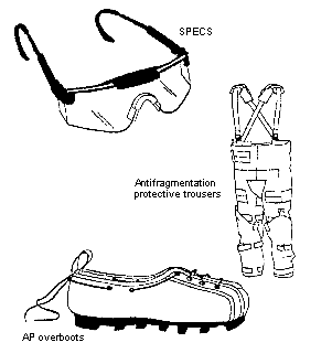
Ensure that appropriate personnel wear flak vests or IBASIC ( Figure E-5). |
|
Ensure that all vehicles have tow cables in the front and the rear, and plan recovery assets for extraction purposes. |
|
Ensure that all vehicles carrying troops have hardening (sandbags on floors and sides). |
|
Provide MP and explosive-sniffing dogs to help in clearance operations and provide security for convoys during and after clearing operations. |
|
Designate a controlling, coordinating, and supporting HQ for route movement. |
|
Designate, recognize, and include the following minefield indicators as part of company-team rehearsals:
|
|
Designate a reserve force (at least platoon-size) that is mechanized or air-assault capable. |
|
Ensure that proper rehearsals are planned and conducted. As a minimum, the unit should rehearse actions at the obstacle, actions on enemy contact, casualty evacuation, and control of COBs. |
|
Ensure that the unit has a clear understanding of the mission, the intent, and the end state. For example, the clearing-unit commander should understand that his unit must clear the road width, including the shoulders, and secure the route. |
|
|
Ensure that PSYOP/CA support the counterintelligence effort by conducting civilian interviews. |
|
Direct civilians along the MSR to the displaced-personnel holding areas or along the routes that the unit has indicated for use. |
|
Employ PSYOP/CA teams forward to disperse civilians and provide traffic management to isolate the route during clearance operations. |
|
Task Organization
E-22. A brigade or battalion TF normally conducts clearance-in-zone operations. To clear a route, the battalion TF focuses a company team as the main effort on the proposed MSR. Table E-1 shows a sample task organization for a route clearance.
Support Force
The support force provides security for the breach force and neutralizes hostile forces. In rugged terrain or highly mined areas, moving the support force on the flanks may be too risky. In this situation, aviation assets may be used to provide flank security while ground forces provide rear security. The support force may also be tasked to search for suspected off-route mines.
Security Force
E-24. The security force is prepared to maneuver and destroy enemy forces that the support force cannot neutralize. The security force may be comprised of maneuver and engineer forces augmented with a medical team, a psychological operations (PSYOP) team, and an EOD team. Additionally, the security force may be supported by a mortar section.
Sweep Force
E-25. The sweep force is comprised of maneuver and engineer forces with detection equipment. The sweep force sweeps the route and reduces mine and explosive threats. As in breaching operations, the sweep force consists of a security element and a reduction element. The security element provides local security for the sweep force. The reduction element consists of sweep teams (personnel and equipment) to reduce obstacles and clear mines.
E-26. A sweep team is a trained detection team that searches for mines and explosive devices. The organization of the sweep team depends on the type of sweep mission, the length and width of the road to be cleared, the time and equipment available, and the surface composition (pavement, gravel, dirt) of the road to be swept. A dismounted platoon-size element can normally clear a 6-meter-wide path, and a squad-size element can normally clear a 2-meter-wide path. Mounted detection equipment, such as the IVMMD, can detect mines along a 3-meter-wide path. See FM 20-32 for detailed information on the composition of a sweep team.
