Obstacle-Reduction Techniques
Obstacle reduction is the physical creation of a lane through an obstacle. It is a fundamental of breaching operations as discussed in earlier chapters. A number of tasks (detecting, reporting, reducing, proofing, and marking) directly support or are included in obstacle reduction.
Detecting
C-1. Detection is the actual confirmation of the location of obstacles. It may be accomplished through recon, or it may be unintentional (such as a vehicle running into a mine). Detection is used in conjunction with intelligence-gathering operations, bypass recons, and breaching and clearing operations. There are four types of detection methods—visual, physical (probing), electronic, and mechanical.
Visual
C-2. Visual detection is part of all combat operations. Personnel visually inspect the terrain for the following obstacle indicators:
- Trip wires.
- Signs of road repair (such as new fill or paving, road patches, ditching, and culvert work).
- Signs placed on trees, posts, or stakes. Threat forces mark their minefields to protect their own forces.
- Dead animals.
- Damaged vehicles.
- Disturbances in previous tire tracks or tracks that stop unexplainably.
- Wires leading away from the side of the road. They may be firing wires that are partially buried.
- Odd features in the ground or patterns that are not present in nature. Plant growth may wilt or change color, rain may wash away some of the cover, the cover may sink or crack around the edges, or the material covering the mines may look like mounds of dirt.
- Civilians who may know where mines or booby traps are located in the residential area. Civilians staying away from certain places or out of certain buildings are good indications of the presence of mines or booby traps. Question civilians to determine the exact locations.
- Pieces of wood or other debris on a road. They may be indicative of pressure or pressure-release firing devices (FDs). These devices may be on the surface or partially buried.
- Patterns of objects that could be used as a sighting line. An enemy can use mines that are fired by command, so road shoulders and areas close to the objects should be searched.
- Berms. They may indicate the presence of an AT ditch.
Physical
C-3. Physical detection (probing) is very time-consuming and is used primarily for mine-clearing operations and self-extraction. Detection of mines by visual or electronic methods should be confirmed by probing. Use the following procedures and techniques when probing for mines:
- Roll up your sleeves and remove your jewelry to increase sensitivity. Wear a Kevlar? helmet, with the chin strap buckled, and a protective fragmentation vest.
- Stay close to the ground and move in a prone position to reduce the effects of an accidental blast. When moving into a prone position—
- Squat down without touching your knees to the ground.
- Scan forward up to 2 meters and to the sides up to 3 meters for mine indicators.
- Probe the area around your feet and as far forward as possible.
- Kneel on the ground after the area is found to be clear, and continue probing forward until you are in a prone position.
- Use sight and touch to detect trip wires, fuses, and pressure prongs.
- Use a slender, nonmetallic object as a probe.
- Probe every 5 centimeters across a 1-meter front.
- Push the probe into the ground gently at an angle that is less than 45 degrees.
-
Apply just enough pressure on the probe to sink it slowly into the ground.
- Pick the soil away carefully with the tip of the probe. Remove the loose dirt by hand if the probe encounters resistance and does not go into the ground freely. Take care to prevent detonating the mine.
- Stop probing and use two fingers from each hand to carefully remove the surrounding soil when a solid object is touched and identify the object.
- Remove enough soil to show the mine type (if the object is a mine) and mark its location. Do not attempt to remove or disarm the mine. Use explosives to destroy detected mines in place or use a grappling hook and rope to cause mines to self-detonate. Do not use metal grappling hooks on magnetic-fused mines.
DANGERUse extreme caution when probing. If the probe is pushed straight down, its tip may detonate a pressure fuse. |
C-4. Probing is extremely stressful and tedious. The senior leader must set a limit to the time a prober will actually probe. To determine a reasonable time, the leader must consider METT-TC factors, weather conditions, the threat level, the unit's stress level, and the prober's fatigue level and state of mind. As a rule, 20 to 30 minutes is the maximum amount of time that an individual can probe effectively.
Electronic
C-5. Electronic detection is effective for locating mines, but this method is time-consuming and exposes personnel to enemy fire. In addition, suspected mines must be confirmed by probing.
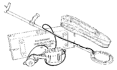
C-6. The AN/PSS-12 mine detector ( Figure C-1 ) can only detect metal, but most mines have metal components in their design. The detector can locate and identify plastic or wooden mines by a slight metallic signature. Employment and operation procedures for the AN/PSS-12 are discussed in FM 20-32 , and technical data is available in Technical Manual (TM) 5-6665-298-10 . The detector is handheld and identifies suspected mines by an audio signal in the headphones.
|
|
C-7. As in probing, consideration must be taken for the maximum amount of time an individual can operate the detector. As a rule, 20 to 30 minutes is the maximum amount of time an individual can use the detector effectively.
Mechanical
C-8. The track-width mine roller is a mechanical minefield-detection system. It is most effectively deployed to lead columns on route movement, but it can be used to precede tactical formations. In column movement, unit vehicles travel a narrow path and one or two mine rollers can effectively detect mines in the path. Mine rollers can also be used to detect minefields in front of deployed tactical formations, although more than one roller is required for a good probability of detection.
Reporting
C-9. Intelligence concerning enemy minefields is reported by the fastest means available. Spot reports (SPOTREPs) are the tactical commander's most common source of minefield intelligence. They originate from patrols that have been sent on specific minefield recon missions or from units that have discovered mine information in the course of their normal operations. The information is transmitted to higher HQ.
Reducing
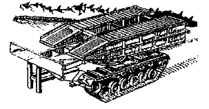
C-10. Obstacle-reduction and clearing equipment is broken down into explosive, mechanical, electronic, and manual. Combat engineers and the operators of reduction assets practice and become proficient in these reduction means. They integrate them into breach drills of units they support. The team applies different tactics, techniques, and procedures (TTP) to breach drills and prepares and rehearses them as part of the TF plan. Tables C-1 through C-4 provide a summary of the effectiveness of reduction assets against the various types of obstacles that may be encountered.
Explosive
C-11. The different types of explosive minefield-reduction and clearing equipment are discussed below.
M58A4 Mine-Clearing Line Charge
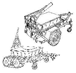
C-12. The MICLIC ( Figure C-2 ) is a rocket-propelled, explosive line charge. It is used to reduce minefields that contain single-impulse, pressure-activated AT mines and mechanically activated AP mines. It clears a 14- by 100-meter path. The MICLIC has a 62-meter standoff distance from the launcher to the detonation point. The MICLIC's effectiveness is limited against prong AP mines, magnetically activated mines (including some SCATMINEs), top-attack mines, side-attack mines, and mines containing multiple-impulse or delay-time fuses. It also has little effect on other obstacles, such as log and concrete barriers, antivehicular ditches, and walls. The shock effect and the psychological impact of the detonation make the MICLIC a useful weapon in a close fight or in urban areas.
|
|
NOTE: See Figures C-3 and C-4 for information on the MICLIC's surface danger zone.
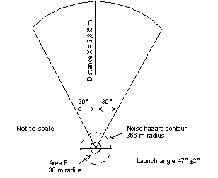
|
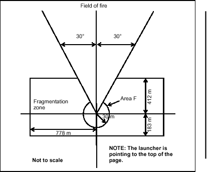
|
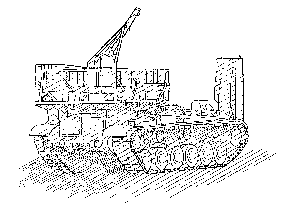
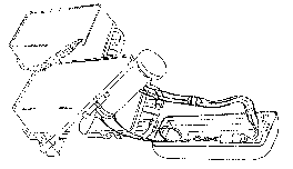
C-13. The MICLIC is mounted on a rubber-tired trailer, or two MICLICs can be mounted on an AVLB, with the bridge downloaded using a fabricated I-beam frame. Procedures for mounting the MICLIC on the AVLB are outlined in TM 9-1375-215-14&P . This is called an armored vehicle-launched MICLIC (AVLM) ( Figure C-5 ) and may be the preferred system because no trailer is involved to hinder the mobility of the vehicle.
|
|
C-14. Towing vehicles for the trailer-mounted MICLIC are an M113 armored personnel carrier (APC), an M9 ACE, a 5-ton wheeled vehicle, and a 2-ton wheeled vehicle. The trailer limits the MICLIC's mobility in rough terrain and degrades the maneuverability of the towing vehicle, thereby increasing vulnerability. Since the MICLIC is critical to the breaching operation, it is moved to the point of breach along easily trafficable, covered, and concealed routes. This effectively prevents the towing vehicle from performing any other task (firing or maneuvering) or serving as an engineer squad vehicle unless MICLIC employment is the squad's only mission. This is an important consideration when selecting the towing vehicle because it must be solely dedicated to the mission.
C-15. The MICLIC can be fired from within an armored vehicle without exposing soldiers to fires, although the prefiring preparations must be done at a covered and concealed location near the point of breach. The initiating cable is brought into the vehicle through the hatch, which must be left ajar, or through the portal of the periscope, which has been removed. Therefore, the crew is not afforded NBC protection. When the MICLIC is fired from a wheeled vehicle, the crew must move to a covered position outside the backblast area. The special-purpose cable on the firing control switch is long enough to allow adequate standoff.
C-16. The vehicle operator must be proficient in all aspects of preparing and deploying the MICLIC, including the critical aspect of selecting the optimum point of breach. Although the engineer platoon leader or the breach force commander directs the operator to the point of breach, ensuring that the operator can independently accomplish the task will simplify the operation and greatly enhance its likelihood of success. The towing vehicle and the operator must be selected well in advance and be dedicated solely to the task. The operator must be included in all rehearsals and planning sessions and, if possible, during leader recons. The MICLIC crew and the breaching force must ensure that misfire/malfunction drills are addressed during the unit rehearsal.
C-17. Each MICLIC trailer transports and fires one charge, and then it must be reloaded. The AVLM can fire both MICLICs before reloading. The loaded-charge container weighs 1,283 kilograms, so a lifting device such as a 5-ton wrecker or a heavy expanded mobility tactical truck (HEMTT) is needed. Reloading, which can be done by an experienced crew in about 20 minutes, entails loading a rocket on the rail and lifting a new charge container onto the launcher. The reloading operation must be done in a covered and concealed location.
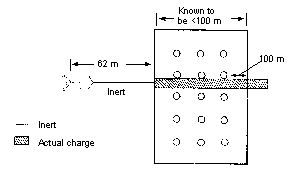
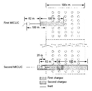
C-18. The exact limits and depth of an enemy minefield are seldom known before a breach. This is particularly true when the situation is unclear and the minefield is encountered simultaneously with enemy contact. The first and only indication that a unit is in a minefield may be when a vehicle encounters a mine. The minefield's leading edge may still be an uncertainty because the vehicle could have hit a mine in an interior row. The number of MICLICs needed to clear a single lane through a minefield—
- Less than 100 meters deep is one (see Figure C-6). The minefield's leading edge is identified and, if possible, confirmed by recon. The MICLIC is deployed from a minimum standoff distance of 62 meters from the minefield's leading edge.
- More than 100 meters deep or of uncertain depth is two or more (see Figure C-7). If the leading edge cannot be identified, the MICLIC is deployed 100 meters from the possible edge or stricken vehicle. When the first MICLIC is detonated, a second MICLIC moves 25 meters into the first MICLIC's path and fires its charge. This extends the lane an additional 87 meters. Additional MICLICs are used for minefields of extreme depth, and each one moves down the lane 25 meters into the path created by the previous charge.
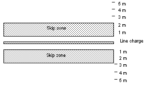
C-19. The neutralization of mines by blast depends on the peak pressure and the impulse. For the MICLIC, the impulse is at a maximum of 3 meters from the line charge (on both sides) and decreases the closer it gets toward the line charge to a minimum of 1 meter from the line charge. This decrease on impulse causes a skip zone (see Figure C-8). This does not mean that neutralization is equal to zero percent; it means that it is not equal to 100 percent. Mines that are buried deeper than 10 centimeters and located 1 to 2 meters from the line charge have a high probability of not being neutralized.
Antipersonnel Obstacle Breaching System
C-20. The Antipersonnel Obstacle Breaching System (APOBS) ( Figure C-9 ) is a man-portable device that is capable of quickly creating a footpath through AP mines and wire entanglements. The APOBS is normally used by combat engineers, infantry soldiers, or dismounted armored cavalry personnel. It provides a lightweight, self-contained, two-man, portable line charge that is rocket-propelled over AP obstacles from a standoff position away from the obstacle's edge.
|
|
C-21. For dismounted operations, the APOBS is carried in 25-kilogram backpacks by no more than two soldiers for a maximum of 2 kilometers. One backpack assembly consists of a rocket-motor launch mechanism containing a 25-meter line-charge segment and 60 attached grenades. The other backpack assembly contains a 20-meter line-charge segment and 48 attached grenades. The total weight of the APOBS is about 54 kilograms. It is capable of breaching a footpath about 0.6 by 45 meters and is fired from a 25-meter standoff.
M1A1/M1A2 Bangalore Torpedo
C-22. The bangalore torpedo ( Figure C-10 ) is a manually emplaced, explosive-filled pipe that was designed as a wire breaching device, but it is also effective against simple pressure-activated AP mines. It is issued as a demolition kit and consists of ten 1.5-meter tubes. Each tube contains 4 kilograms of HEs and weighs 6 kilograms. The kit clears a 1- by 15-meter lane.
|
|
C-23. The bangalore torpedo is used by dismounted infantry and engineer soldiers. An individual soldier or a pair of soldiers connects the number of sections needed and pushes the torpedo through the AP minefield before priming it. A detailed recon is conducted before using the bangalore torpedo to ensure that trip wires have not been used. The bangalore torpedo generates one short impulse and is not effective against pronged, double-impulse, or pressure-resistant AP and AT mines.
Mechanical
C-24. MCBs and MCRs are fielded as armor battalion countermine sets that contain 12 MCBs and 4 MCRs. Blades create lanes through minefields, while rollers are used to detect minefields and proof lanes created by other means. Rollers are not a good primary system for lane reduction because multiple mine detonations may destroy the roller system and the vehicle pushing it. (The roller is designed to resist four conventional-mine [22.5 pounds HE] or three SCATMINE strikes, depending on the mine type.)
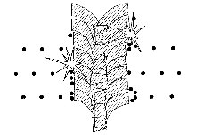
C-25. The ACE and dozer blades were not designed for reducing minefields and should only be used as a last resort. Using them is extremely time-consuming and hazardous to the crew and equipment. However, ACEs can effectively clear a lane through AP scatterable minefields because they sustain little or no damage and offer protection to the crew. When using a dozer to clear a path through a minefield, the operator is exposed to mine effects. Before clearing begins, sandbag or up-armor the operator's cabin and clear the lane of trip wires. When using an engineer blade to clear a path through a scatterable minefield, use the skim technique ( Figure C-11 ). Start skimming 100 meters from the suspected leading edge of the minefield.
|
|
C-26. The ACE and dozer blades are very effective against AT ditches and gaps. Normally, during a breaching operation, dozers will not be available due to their inability to keep pace with the attacking forces. Although a single dozer or an ACE is capable of reducing an AT ditch, a technique that has been successfully used and has decreased the time to reduce an AT ditch/gap is to use two ACEs or an ACE/dozer team. When using this technique, position one ACE parallel to the AT ditch and push dirt in front of the second ACE or dozer that is oriented perpendicular to the AT ditch. Use an ACE to push dirt into the AT ditch.
Mine-Clearing Blade
C-27. The MCB ( Figure C-12) is used to remove land mines and create a lane in a minefield. It consists of a blade arrangement with scarifying teeth to extract mines, a moldboard to cast mines aside, and leveling skids to control the blade's depth.
|
|
C-28. The MCB lifts and pushes mines, which are surface-laid or buried up to 31 centimeters deep, to the side of track-width lanes. The blade has three depth settings—21, 25, and 31 centimeters. The blade creates a 1.5-meter cleared path in front of each track. Figure C-13 shows the inside clearance distances between the tracks of common tracked vehicles in relation to the uncleared area left by the MCB.
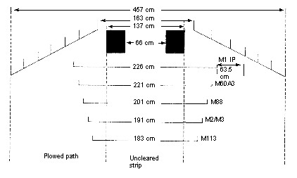
|
C-29. Mines armed with AHDs, magnetic fuses, or seismic fuses may be activated when they are lifted by the blade; and they may disable the blade. Mines lifted by the blade are left in the spoil on each side of the furrowed path and remain a hazard until they are removed. Double-impulse mines that are lifted into the spoil on the side can function into the hull of the plowing vehicle.
C-30. The skid shoe for each blade exerts adequate pressure to activate most single-impulse mines, which effectively clears a section of the centerline by explosive detonation. This action may disable the blade. Multiple-impulse pressure fuses encountered by the skid shoe are not defeated. A dog-bone assembly between the blades defeats tilt-rod mines. The improved dog-bone assembly (IDA) projects a magnetic signature and defeats tilt-rod and magnetic mines.
C-31. The MCB weighs about 3,150 kilograms and can be mounted on an M1 tank without special preparation or modification. Mounting requires lift capability and takes up to an hour, so it must be mounted well in advance of the mission. It is not easy to mount or transfer the MCB to another tank under battle-space conditions.
C-32. Once mounted, an electric motor raises and lowers the blade. When the blade is raised, it minimally effects the M1's maneuverability and speed. This will not greatly impact the use of the weapon system except when the blade is in operation. The MCB is also equipped with an emergency, quick-disconnect feature.
C-33. The M1 tank crew should maintain a speed of 8 to 10 kph while plowing, depending on soil conditions. The tank cannot maneuver but must continue in a straight path through the minefield to avoid damaging the blade. The main gun must be traversed to the side during plowing because mine detonation under the blade may cause the gun to be thrown violently into the air, damaging the tube. The area selected for the lane must be relatively flat and free of rocks or other obstacles.
C-34. The operator begins plowing about 100 meters from the estimated leading edge of the minefield. He creates a lane extending another 100 meters beyond the estimated far edge of the minefield to ensure that the lane extends through the entire minefield. Multiple vehicles using the lane will deepen the cut made by the MCB, and pressure-fused mines left in the uncleared strip will be dangerous. The uncleared strip should be cleared as soon as possible.
Mine-Clearing Roller
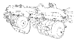
C-35. The MCR ( Figure C-14) consists of a roller assembly, a mounting kit, and a hand winch. The roller assembly weighs about 9,072 kilograms and consists of two push beams mounted to the front of the tank. The rollers are designed to defeat most single-pulse, pressure-activated AT and AP mines. The roller creates a 1.1-meter-wide cleared path in front of each track.
|
|
C-36. Figure C-15 shows the inside clearance distances between the tracks of common tracked vehicles in relation to the uncleared area left by the MCR. An IDA and a chain between the rollers defeats tilt-rod mines. The IDA can be fitted to the roller. The roller is designed to withstand multiple mine explosions before damage; however, this depends on the size of the mines. Large blasts may destroy the roller or the vehicle or injure the crew.
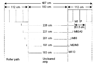
|
C-37. The roller can be mounted on an M1 or M60 tank that is modified with a permanently attached mine-roller mounting kit. Mounting the roller to a tank is a cumbersome, time-consuming operation because it is very difficult under battle-space conditions and requires lift capability. The roller tank is limited to a speed of 5 to 15 kph. When used in a suspected minefield, the MCR must travel in a relatively straight path. Tight turns may cause the roller to deviate from the path of the track and leave the tank vulnerable to mines. Ground fluctuations, bumps, and berms may cause the roller to lift from the ground and miss mines.
C-38. Due to the roller tank's weight and width, units must use caution when crossing an AVLB. In this situation, the curbing from the bridge is removed. To prevent damage to the bridge's hydraulic line, the tank driver uses a strap to lift the IDA and the chain when crossing the bridge. The main gun must be traversed to the side when a mine encounter is possible or imminent. A mine blast can throw the roller or parts of the roller violently into the air and damage the tube. The main gun should only be fired from a temporary halt.
C-39. When the situation and the mission permit, MCRs are used with lead/security elements of the breach force to detect the minefield's leading edge. Rollers are also used to proof lanes in obstacles that are reduced by other means, such as a MICLIC or an MCB. The roller may also be used to lead a supported element traveling in a tactical formation other than a column, but it is less effective than other methods because—
- A vehicle that is not directly behind the roller may encounter mines.
- The roller may travel well into or completely through a widely spaced minefield without encountering a mine, thus giving the formation a false sense of security.
- A mine encountered by the roller may not be on the minefield's leading edge.
- The roller vehicle is extremely vulnerable since it can only use its weapon system from a temporary halt.
C-40. If rollers are to participate in a breaching operation, they must be mounted before rehearsals. Unmounted rollers that are not being used for the mission are carried in the TF formation on M916 tractor trailers. Rollers require lift capability (such as an M88), a secure location, and 30 to 60 minutes to mount on a tank that is fitted with a mounting kit.
Panther
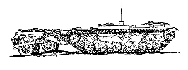
C-41. The M60 Panther ( Figure C-16 ) is one of several developmental countermine systems that US forces used during operations Joint Endeavor and Joint TF Eagle. The Panther is a remotely controlled vehicle with mine rollers, and it is used to proof lanes and assembly areas. The system consists of a turretless M60 tank, Israeli mine rollers, an antimagnetic actuating device, and a remote control unit (RCU) that is mounted in a separate vehicle. Additionally, a remote video camera allows the operator to see the road ahead.
|
|
C-42. During route-clearance or proofing operations, a Panther is the lead vehicle. It is followed closely by an armored control vehicle, usually an M113. The control vehicle contains the Panther operator, the RCU, and the monitor. The monitor displays the route being proofed or cleared through a camera mounted on the Panther. The Panther is controlled from the commander's cupola or troop hatch of the control vehicle. The control vehicle should be about 200 to 300 meters behind the Panther, and its hatches should be secured open. Crew members in the control vehicle should be wearing Improved Body Armor System, Individual Countermine (IBASIC) protective garments.
C-43. Mine rollers can be raised for limited travel while mounted on the Panther. If the distance is excessive, the rollers must be transported on a cargo carrier. Rollers must be adjusted before every mission to ensure that they have contact with the ground and that their weight is uniformly distributed. Conduct at least three passes to ensure proper coverage and overlap of rollers. Passes should have a minimum of 30 centimeters overlap. Inside roller distances are the same as an MCR.
M1 Grizzly
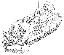
C-44. The Grizzly ( Figure C-17 ) provides the capability for breaching obstacles comprised of mines, wire, posts, rubble, and tank ditches to create a lane for other vehicles to follow. The Grizzly's primary features are a full-width, 4.2-meter MCB and a power arm. The power arm has a reach of 9 meters and a bucket capacity of 1.2 cubic meters. Its primary missions are to reduce berms and fill AT ditches.
|
|
C-45. The Grizzly lifts and pushes mines, which are surface-laid or buried up to 31 centimeters deep, to the side of full-width lanes. The blade has multiple depth settings, depending on the mission, and it creates a 4.2-meter-wide cleared path. When plowing, the Grizzly is restricted to less than 10 kph, depending on soil conditions. The operator begins plowing about 100 meters from the estimated leading edge of the minefield. He creates a lane extending another 100 meters beyond the estimated far edge of the minefield to ensure that the lane extends through the entire minefield.
C-46. The Grizzly has integrated digital features to enhance battlefield awareness. Some of the digital features are thermal and video cameras, ground-speed sensors, terrain-mapping sensors, and an integrated commander's control station.
Mine-Clearing/Armor-Protection Kit
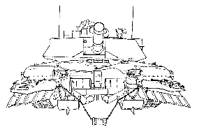
C-47. The mine-clearing/armor-protection (MCAP) kit consists of two parts—the mine-clearing rake and the armor protection.
- Mine-clearing rake. The rake uses a tine that is mounted on a diagonal beam. The rake assembly is designed to sift through the soil, lift out mines, and windrow buried and surface-laid mines to the right of the vehicle. The system clears a 30-centimeter-deep path through a minefield. The rake has a skid shoe that acts as a depth control guide for the operator.
- Armor protection. The armor protects the crew against mine blast, small-arms fire, and artillery fire. Protection is also provided for the engine, the fuel tank, and exposed hydraulic cylinders and lines. Ballistic glass blocks are provided at each vision port to permit unrestricted view and operation of the vehicle and the equipment.
The MCAP is mounted on a D7 dozer to perform minefield reduction and lane widening. Proofing the lane must be conducted after the dozer has cleared the lane because some AP mines may still be left in the lane.
Armored Vehicle-Launched Bridge
C-48. The AVLB ( Figure C-18 ) is carried on a launcher (a modified M48A5 or M60A1 chassis) and weighs 15 tons. A buttoned-up, two-man crew can launch the AVLB in 2 to 5 minutes. The AVLB can be retrieved from either end; however, one man is exposed to fire while guiding and connecting it. The AVLB is capable of carrying military load class (MLC) 60 (70 with improved bridge) tracked loads across a 17.4-meter gap with unprepared abutments or an 18.3-meter gap with prepared abutments.
|
|
Wolverine
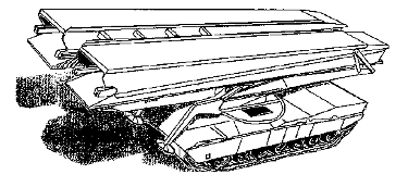
C-50. The AVLB will eventually be replaced by the Wolverine ( Figure C-19 ). The bridge is carried on a launcher (a modified M1 tank chassis) and weighs 12.5 tons. It can be launched in less than 5 minutes by a buttoned-up, two-man crew and can be retrieved from either end of the bridge in less than 10 minutes. The Wolverine can cross an MLC 70 tracked vehicle over 24-meter gaps. The launcher has a maximum speed of 83 kph.
|
|
M9 Armored Combat Earthmover
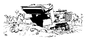
C-51. The M9 ACE ( Figure C-20 ) is capable of performing mobility tasks in support of light and heavy forces. These tasks include gaps and AT ditches. Although an ACE can be used to reduce a scatterable minefield, it should only be used as a last resort.
|
|
Electronic
C-52. The Field-Expedient Countermine System (FECS) is a series of copper coils that fit over the front of tracked and wheeled vehicles. Power is supplied by the vehicle's battery. The coils emit a large magnetic signature that detonates magnetically fused mines located 2 to 5 meters in front of the vehicle. The FECS is designed to defeat magnetically influenced mines only and must be used with other countermine systems.
Manual
C-53. While mechanical and explosive reduction procedures are normally preferred, a unit may have to use manual procedures for the following reasons:
- Explosive and mechanical mobility assets are unavailable (not on hand or nonmission capable).
- Explosive and mechanical mobility assets are ineffective against the type of obstacle or because of terrain limitations (see Table C-1).
- Stealth is required.
C-54. Manual procedures involve dismounted soldiers (usually engineers) using simple explosives or equipment to create a lane through an obstacle or to clear an obstacle. These procedures expose the soldier and may be manpower- and time-intensive. However, this method works in most situations and under most conditions. Certain types of terrain, weather, and sophisticated fuses can severely degrade the effectiveness of rollers, plows, and line charges.
Techniques
C-55. As discussed, manual procedures are effective against all obstacles under all conditions. Most types of obstacles do not cause casualties directly, but minefields have the potential to cause direct casualties. The enemy possesses a significant mechanical, mine-burying capability. It has the capacity and the propensity for the labor-intensive effort required to bury mines by hand; however, the enemy often lays mines on the surface. Buried mines are usually found in a highly prepared defense. When training for the reduction of surface-laid and buried minefields, always assume the presence of AHDs and trip wires until proven otherwise. Manual reduction of surface-laid and buried minefields is discussed below:
- Surface-laid minefield. Engineers first use grapnel hooks from covered positions to check for trip wires in the lane. The limited range of the tossed hook requires the procedure to be repeated through the estimated depth of the obstacle. A demolition team then moves through the lane. The team places a line main down the center of the lane, ties the line from the explosive into the line main, and places blocks of explosive next to surface-laid mines. After the mines are detonated, the team makes a visual check to ensure that all mines were cleared before directing a proofing roller and other traffic through the lane. Members of the demolition team are assigned special tasks, such as grappler, detonating-cord man, and demolitions man. All members should be cross-trained on all procedures. Demolitions are prepared for use before arriving at the point of breach. An engineer platoon uses squads in series through the minefield to clear a lane for a company team. The platoon must rehearse reduction procedures until execution is flawless, quick, and technically safe. During reduction, the engineer platoon will be exposed in the lane for 5 minutes or more depending on the mission, the minefield depth, and the platoon's level of training.
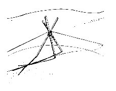
- Buried minefield. Manually reducing a buried minefield is extremely difficult to perform as part of a breaching operation. If mine burrows are not easily seen, mine detectors and probes must be used to locate mines. Mines are then destroyed by hand-emplaced charges. As an alternative, mines can be removed by using a grappling hook and, if necessary, a tripod ( Figure C-21 ). Using a tripod provides vertical lift on a mine, making it easier to pull the mine out of the hole.
|
|
C-56. The platoon leader organizes soldiers into teams with distinct, rehearsed missions including grappling, detecting, marking, probing, and emplacing demolitions and detonating cord. The platoon is exposed in the obstacle for long periods of time.
Grappling Hook
C-57. The grappling hook (grapnel) is a multipurpose tool that is used for manual obstacle reduction. Soldiers use it to detonate mines from a standoff position by activating trip wires and AHDs. After the grapnel is used to clear trip wires in a lane, dismounted engineers can move through the minefield, visually locate surface-laid mines, and prepare mines for demolition. In buried minefields, soldiers grapple, and then enter the minefield with mine detectors and probes. There are two types of grapnel hooks—hand-thrown and weapon-launched.
- Hand-thrown. A 60+-meter light rope is attached to the grapnel for hand throwing. The throwing range is usually no more than 25 meters. The excess rope is used for the standoff distance when the thrower begins grappling. The thrower tosses the grapnel and seeks cover before the grapnel and rope touch the ground in case their impact detonates a mine. He then moves backward, reaches the end of the excess rope, takes cover, and begins grappling. Once the grapnel is recovered, the thrower moves forward to the original position, tosses the grapnel, and repeats the procedure at least twice. He then moves to the end of the grappled area and repeats this sequence through the depth of the minefield.
- Weapon-launched. A 150-meter lightweight rope is attached to a lightweight grapnel that is designed to be fired from an M16A1 or M16A2 rifle using an M855 cartridge. The grapnel is pushed onto the rifle muzzle with the opening of the retrieval-rope bag oriented toward the minefield. The firer is located 25 meters from the minefield's leading edge and aims the rifle muzzle at a 30- to 40-degree angle for maximum range. Once fired, the grapnel travels 75 to 100 meters from the firer's position. After the weapon-launched grapnel hook (WLGH) has been fired, the firer secures the rope, moves 60 meters from the minefield, moves into a prone position, and begins to grapple. The WLGH can be used only once to clear a minefield, but it can be reused up to 20 times for training because blanks are used to fire it.
C-58. Multiple grapplers can clear a lane of trip wires quickly and thoroughly, but they must time their efforts and follow procedures simultaneously. A hit on a trip wire or a pressure fuse can destroy the hook and the cord, so engineers should carry extras.
