Appendix B

Threat Mine Operations

This appendix is intended to complement the information presented in other manuals on threat obstacle tactics. Commanders should use this information to give added realism to unclassified staff and combined-arms team training. Obstacle employment norms can change with METT-TC factors for a given AO. Therefore, preoperational training on templating, intelligence, recon, and reduction procedures must be based on the best information available before deployment.

Mine Operations

B-1. Threat formations contain considerable organic minefield-emplacement capability. Threat rapid-mining capability presents a serious challenge to friendly maneuver.

B-2. Armored tracked mine layers known as GMZs ( Figure B-1 ) dispense mines at a predetermined spacing of 5.5 meters. Three GMZs can lay a 1,200-meter, three-row minefield, containing 624 mines, in 26 minutes. (This does not include the 12- to 15-minute reload and travel times; travel and reload times increase during limited visibility.) Doctrinally, this minefield would be broken into several minefields, each 200 to 300 meters long. Mine-laying helicopters also support threat mine operations. The HIP and HIND-D helicopters carry two or three dispenser pods of AP or AT mines. Artillery-fired SCATMINEs can also support threat mine operations.

Figure B-1. GMZ Armored Tracked Mine Layer


B-3. Threat armies use obstacles extensively throughout the depth of their defense, and their tactics are chosen well. A threat rapidly emplaced minefield consists of three or four 200- to 300-meter rows, spaced 20 to 40 meters apart, with mines spaced 4 to 6 meters apart.

B-4. Table B-1 provides detailed information on standard threat AT and AP minefields. Terrain and tactical situations dictate the actual dimensions and distances of minefields.

Table B-1. Normal Parameters for Threat-Style Minefields

AT Minefields

Front (situation-dependent)

200 to 300 meters

Depth

40 to 120 meters

Number of rows

3 or 4

Distance between rows

20 to 40 meters

Distance between mines

4 to 6 meters for antitrack mines; 9 to 12 meters for antihull mines

Outlay, normal

550 to 750 antitrack mines per kilometer; 300 to 400 antihull mines per kilometer

Outlay, increased effect

1,000+ antitrack mines per kilometer; 500+ antihull mines per kilometer

Probability of destruction

57 percent for antitrack mines (750 per kilometer); 85 percent for antihull mines (400 per kilometer)

AP Minefields

Front (situation-dependent)

30 to 300 meters

Depth

10 to 150 meters

Distance between rows

5+ meters for blast mines; 25 to 50 meters for fragmentation mines

Distance between mines

1 meter for blast mines; 50 meters (or twice the lethal radius of fragmentation) for fragmentation mines

Outlay, normal

2,000 to 3,000 HE/blast mines per kilometer; 100 to 300 fragmentation mines per kilometer

Outlay, increased effect

2 to 3 times the normal outlay

Probability of destruction

15 to 20 percent for HE/blast mines (2,000 per kilometer); 10 to 15 percent for fragmentation mines (100 per kilometer)

B-5. Figure B-2 shows a standard rapidly emplaced minefield. The threat army typically uses such a minefield when they are in a hasty defense (offense is temporarily stalled).
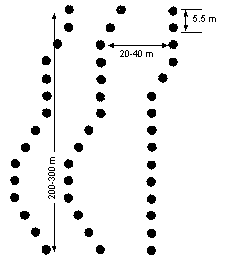
Figure B-2. Threat-Style Rapidly Emplaced Minefield


B-6. Figure B-3 shows a standard antitrack minefield.
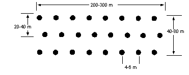
Figure B-3. Threat-Style Antitrack Minefield


B-7. Figure B-4 shows a standard antihull minefield.
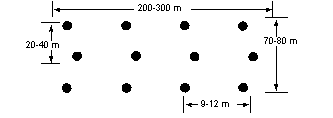
Figure B-4. Threat-Style Antihull Minefield


B-8. Figure B-5 shows a standard AP minefield.
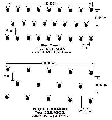
Figure B-5. Threat-Style AP Minefield


B-9. Threat armies also emplace mixed minefields. They are not the same as US mixed minefields. Threat armies normally emplace three rows of AT mines, then several rows of AP mines. AT and AP mines are not normally mixed in the same row.

B-10. Threat engineers use two fundamental drills to emplace mines:

B-11. Special precautions are taken when emplacing AP minefields. Threat doctrine only allows PMN mines to be surface-laid from mine layers. POMZ-2M mines are emplaced with the truck-and-tray technique. Extra effort is required to assemble, emplace, and deploy the trip wire and to camouflage the POMZ-2M mine.

B-12. Threat forces may also have ground-emplaced SCATMINE capability. One such system is the UMZ SCATMINE system ( Figure B-6 ). The UMZ consists of six firing modules mounted on the back of a Zil-131 truck. Each module has 30 firing tubes, for a total of 180 firing tubes per system. Depending on the type of minefield desired, the UMZ can lay 180 to 11,520 mines without reloading. The UMZ can launch an AT or AP minefield 30 to 60 meters from the vehicle while the truck is driving 10 to 40 kilometers per hour (kph). It takes two men 1 to 2 hours to reload the UMZ. One UMZ can lay a three-row minefield, 150 to 1,500 meters long, depending on the type of mine that is used.

Figure B-6. UMZ SCATMINE System


B-13. For hand-emplaced SCATMINEs, there is a man-portable SCATMINE dispenser. The PKM weighs 2.63 kilograms (without the mine canister) and consists of a single launch tube with a base mount, a blasting machine, and a reel of electric ignition wire. The operator loads a propelling charge and a mine canister into the launch tube and mounts the tube on the edge of a trench or firing parapet. He then aims the tube, connects the ignition wire to the tube, and moves to a safe distance. At an initiating point, the operator connects the ignition wire to the blasting machine and initiates the system. The PKM propels the canister 30 to 100 meters, depending on the type of mine. It lays an AP minefield that is 10 by 20 meters (POM-1S or PFM-1S mine canister) or 10 by 40 meters (POM-2S mine canister). It takes a trained operator 5 minutes to set up the PKM and create a minefield. The PKM can also be used to launch the PTM-1S and PTM-3 AT mine canisters.

B-14. Threat forces use the PKM to lay minefields that protect subunit positions and flanks and the boundaries between subunits. PKM-laid minefields also cover firing lines and gaps in combat formations. The PKM can quickly close breaches in existing minefields and increase the density of mines on armor AAs.

B-15. The type and complexity of an obstacle depend on the installing unit. Maneuver and artillery soldiers usually install simple single-system minefields that are protective in nature. Engineer soldiers install complex obstacles that can include AHDs. Engineer obstacle placement is usually equipment-intensive. Threat engineer effort generally concentrates on tactical obstacles unless maneuver soldiers are unable to employ the necessary protective obstacles. Threat units continue to improve obstacles, supporting their positions by marking the friendly side of the obstacles, burying mines, and adding AHDs.

Foreign-Mine Data

B-16. Tables B-2 through B-7 provide details on foreign AT and AP mines and mine delivery systems.
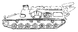
Table B-2. Foreign Track-Width AT Mines

Origin

Mechanically
Planted

Scatterable

Metallic

Nonmetallic

Simple
Pressure

Double
Impulse

Blast
Hardened

AHD

Russia

TM-46
TM-57
TM-62

PTM-1

TM-46
TM-57
TM-62

TM-62B
TM-62D
TM-62P

TM-46
TM-57
TM-62


TM-46
TM-57

TMN-46

China

Type 72

Type 84B

Type 72

Type 72

Type 84B

Type 72

Type 72


Yug

TMM-1


TMM-1

TMA-1
TMA-2
TMA-3
TMA-4
TMA-5

TMA-1
TMA-2
TMA-5


TMA-3
TMA-4

TMM-1
TMA-1
TMA-2
TMA-3
TMA-4
TMA-5

Czech

PT-MI-K
PT-MI-BA III


PT-MI-K
PT-MI-D

PT-MI-BA II
PT-MI-BA III

PT-MI-BA III
PT-MI-D


PT-MI-K
PT-MI-BA II

PT-MI-K
PT-MI-D

Italy

VS-1.6
VS-2.2
TC-.6/6
SB-81

VS-1.6
SB-81


VS-1.6
VS-2.2
TC-.6/6
SB-81


VS-1.6
VS-2.2
TC-3.6
TC-6
SB-81

VS-1.6
VS-2.2

France

M-51
M-52


M-51
M-52

M-51
M-52


M-51

UK

L9 Barmine
MK-7


MK-7

L9 Barmine

L9 Barmine
MK-7

L9 Barmine
MK-7


L9 Barmine

Germany

PM-60
DM-11


DM-21

PM-60
DM-11

PM-60
DM-11
DM-21


PM-60
DM-11
DM-21


Table B-3. Foreign Full-Width AT Mines

Origin

Mechanically
Planted

Scatterable

Tilt Rod

Magnetic
Influence

Seismic
Influence

Coupled

AHD

Russia

TM-62
TM-72
TM-89

PTM-3

TMK-2

TM-62
TM-72
TM-89

TM-62
TM-72
TM-89


TM-62
TM-72
TM-89

China


Type 84C

Type 84A


Type 84A

Yug

TMRP-6

KB-2

TMRP-6

TMRP-6
KB-2


TMRP-6
KB-2

Czech


PT-MI-P


France

HPD series

Lance

M-51
M-52
Model 1954

HPD series


Model 1953

HPD series
M-51
Lance

Hungary

UKB-63


UKB-63


UKB-63

Italy

VS-HCT
VS-HCT-2
SB-MV

VS-SATM1
VS-HCT


VS-HCT
VS-HCT-2
SB-MV
VS-SATM1


Fuse option

VS-HCT
VS-HCT-2
SB-MV
VS-SATM1

Sweden

FFV-028


FFV-028


Fuse 15

FFV-028

UK

L9 Barmine

HB-876

L9 Barmine
MK-7

L9 Barmine
HB-876


L9 Barmine
MK-7
HB-876

Germany

DM-31

AT-2
MIFF

AT-2

DM-31
MIFF


DM-31
AT-2
MIFF

Romania


MC-71


Table B-4. Foreign Pressure-Fused AP Mines

Origin

Scatterable

Low Metal

Simple
Pressure

Small
Diameter

Low-Operating
Threshold

Pronged
Fuse

Blast
Hardened

AHD

Russia

PFM-1


PMN
PMD-6


PMN
PMD-6
PFM-1

OZM series

PMN-2


China

GLD-111

Type 72A
GLD-111

Type 72A
Type 58
GLD-111

GLD-111

Type 72
Type 58
GLD-111


Type 72A
Type 72B

Yug


PMB-1
PMB-2
PMB-3

PMA-1
PMD-1


PMA-1
PMA-3
PMD-1

PROM-1
PROM-2
PMR-3

PMA-2
PMA-3


Czech


PP-MI-D
PP-MI-BA


PP-MI-D

PP-MI-SR
PP-MI-SR II


Italy

TS-50
VS-50
SB-33
VS-MK2

TS-50
SB-33
VS-MK2


Valmara 59
Valmara 69

TS-50
VS-50
SB-33
VS-MK2

VS-50
SB-33
VS-MK2

France


M-59


M-59

M-59


M-59


UK

Ranger


Ranger

Ranger


Germany


DM-11

PPM-2


DM-11


DM-11


Table B-5. Foreign Side-Attack AT Mines

Origin

Command

Break Wire

Influence

AHD

Russia

MON-100/200/500, TM-83

LMG

TM-73/83


Yug


TMRP-6, COBRA


France

MIACAH F1

MIACAH F1

MIACAH F1


UK

L14

L14

AJAX

AJAX

Germany


DM-12


Sweden


FFV-016, AT-4


Table B-6. Foreign Trip-Wire/Break-Wire-Fused AP Mines

Origin

Scatterable

Trip Wire

Break Wire

Russia

POM-2

POMZ-2, OZM series, MON series

OZM series, MON series

China


Type 58, Type 59, Type 66, Type 69


Yug


PROM-1/2/KD, PMR-2/3/4, MRUD

PROM-1/2/KD, PMR-2/3/4, MRUD

Czech


PP-MI-SR, PP-MI-SR II, PP-MI-SK


Italy

VS-SAPFM3

Valmara 59/69, BM-85, P-25, P-40, VS-DAFM1


France


M1951/1955, MAPED F1

M1951/1955

UK


PAD


Germany


DM-31, SM-70


Table B-7. Foreign Mine Delivery Systems

Origin

System

Type 1

Range

Mine Payload

Density 2

Remarks

Russia

BM-21

R

20 km

PTM 1/3, POM-2

1.5

1,000 x 500 m per battery

BM-22

R

35 km

PTM 1/3, POM-2

1.5


BKPI

F, H

NA

PTM 1/3, PFM-1, POM-2

1.5

Lays relatively narrow strips

KSMU

F

NA

PTM 1/3, PFM-1, POM-2

1.5


UMZ

V

NA

PTM 1/3, POM-2

1.5


GMZ/PMZ-4

MP

NA

Varies

0.4 to 1.0

3 systems can emplace 1,200 m with 624 mines in 26 minutes

VMR-1/2

H

NA

Varies

0.4 to 1.0

3 Mi-8s can lay 1,200 to 3,000 m with 1,200 mines

China

Type 83

R

15 km

Type 84

0.5

900 x 800 m per battery

Yug

M87

R

50 km

KB-2

0.5

900 x 500 m per battery

Italy

FIROS 25

R

22 km

VS-HCL, VS-Mk, VS-SAPFM 3

0.5


FIROS 30

R

35 km

VS-HCL, VS-Mk, VS-SAPFM 3

0.5


DAT

H

NA

Varies

1.2

Lays relatively narrow strips of up to 320 AT mines

Istrice

V

NA

SATM1, VS-Mk 2 EL, VS-SAPFM 3

Max 1.6

Typically 360 x 140 m

ST-AT/V

MP

NA

Varies

0.3 to 1.5

240 mines per hour

Grillo 90

MD

NA

SATM1, VS-Mk 2 EL

0.5

5 AT or 15 AP mines per dispenser

Sweden

FFV-5821

MP

NA

FFV-028

0.4 to 1.4

300 buried mines per hour or 500 surface-laid mines per hour

France

Minotaur

V

NA

Lance

0.7

1,200 x 600 m with 800 mines

EBG

V

NA

Lance

1.5

60 x 600 m with 40 mines

155-mm How

A

18 km

Lance


8 mines per round

Matenin

MP

NA

HPD series

0.4 to 1.4

500 mines per hour

UK

JP-233

F

NA

HB 876


430 mines per Tornado aircraft

Barmine layer

MP

NA

L9 Barmine

0.4 to 0.9

Lays up to 700 mines per hour

Ranger

V

NA

L10


1,296 mines per dispenser

Germany

Skorpion

V, H

NA

AT-2

0.4

1,500 x 50 m with 600 mines

MW-1

F

NA

MIFF, MUSPA

0.5

55 to 500 m wide and 200 to 2,500 m

LARS

R

14 km

AT-2

0.5

1,836 AT mines per launcher, 1,000 x 500 m per battery

MARS

R

30 km

AT-2

0.3

1,000 x 500 m with 336 AT mines per launcher

FFV-5821

MP

NA

DM-31

0.4 to 1.4

300 buried mines per hour or 500 surface-laid mines per hour

1 A = artillery, H = helicopter, F = fixed-wing aircraft, R = rocket, V= vehicle dispensed, MD = man-portable dispenser, MP = mechanical planter
2 AT mines per meter of front